Question: Cinema balcony 8m deep and 18 m wide in steel is proposed for cinema hall. Assume suitable data draw the following:
a). part key plan and section scale 1:100 showing structural components of the balcony.
b). cross section of the balcony (in large scale) showing arrangement of structural components and false ceiling details, etc.
Answer: Since cinema balcony space will not allow columns on cantilevered side, we can place steel H sections in U form. So on 8m depth side we will place 3 columns at 4m centre to centre or 4 columns at 2.66m centre to centre (preferred). The sizes of columns will vary slightly depending on span. On 18 m side we can go for 3m centre to centre. These columns will come only on one side leaving the other side columns free for un-obstructed viewing.

The steel columns can be H sections or built-up sections or combined together can be used.
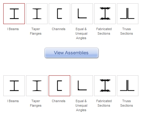
H - sections are popularly known as the rolled steel joists or beams. It consists of two flanges connected by a web. It is designated by overall depth, width of flange and weight per meter length. They are available in various sizes varying from 75mm x 50 mm at 59.84 N to 600 mm x 210 at 976.1 N.

Some more sizes of H sections are given below:
150 mm x 100 mm at 166.77 N
150 mm x 150 mm at 265.85 N
300 mm x 150 mm at 369.84 N
450 mm x 250 mm at 907.43 N
600 mm x 250 mm at 1423.43 N
The R. S. joists are economical in material and they are suitable for floor beams, lintels, columns, etc. The economy in material is achieved by concentrating the material in two flanges where the bending stresses are maximum.
BUILT-UP SECTIONS:
In order to make steel beams and columns of suitable strength and rigidity, the standard sections are built-up or combined together. It is thus possible for a designer in the steel structures to make use of available standard sections of structural steel and prepare a built-up section as per requirements.
Some combinations for your information:
a). One I section with two plates at top and other at bottom. (plates sizes vary from 5 mm to 50 mm with corresponding weights per meter square are 384.55 N and 3850.43 N respectively).
b). Two I sections and two plates one at top and other at bottom (if design requires two plates at top and bottom can also be used).
c). 3 I sections with i) at end of flange of one I section you can place center of web of two I sections one each on either side mirrored. ii) on both sides of vertical web you can place one each I section on either side with flange abutting web mirrored.
d). I section in center and two channel sections on either side.
e). Two channel sections with some gap between two mirrored C sections with two plates on either side.
f). A combined I section built by placing two plates with some gap with four angles placed mirrored and two plates on top and bottom one each.
For our problem at hand we can choose option b). with two I sections of 300 mm x 150 mm at 369.84 N and plate 10 mm at 769.82 N two nos at top and bottom of width 450 mm.
or alternatively we can choose single I section of 450 mm x 250 mm at 907.43 N (I am no expert in steel designs but this is my best educated guess).
please note we will have perimeter main beams on all three sides of balcony of I sections of 450 mm x 250 mm at 907.43 N or alternative you can use castellated beam 250 mm x 600 mm.

(Castellated beams refer to the type of beams which involve expanding a standard rolled steel section in such a way that a predetermined pattern is cut on section webs and the rolled section is cut into two halves. The two halves are joined together by welding and the high points of the web pattern are connected together to form a castellated beam. The castellated beams were commonly used in Europe in 1950s due to the limited ranges of the available steel rolled section and the cheap labour cost. In terms of structural performance, the operation of splitting and expanding the rolled steel sections helps to increase the section modulus of the beams. Moreover, it is versatile for its high strength to weight ratio so that lighter section can be designed with subsequent cost saving in foundation).
Along the depth of 8 m balcony side near the screen you can give lattice girder beam approximately 2.2 meter deep made of mirrored C channels and angles of 75 x 50 x 6 mm welded together with gusset plate of 6mm thick.
please note that the cross section across the width of 8 m deep may have slope of necessary angle to get clear viewing angles. this is approximately 30 cm at every 1.2 m depth of balcony. You can safely take two meter slope in 8 meter deep balcony.
CONNECTIONS IN STEEL WORK:
The various members of a steel framed structure are to be suitably connected for transfer of loads. Following are the methods adopted for connecting the members of steel work:
i). Bolts: When it is desired to have temporary connections, the bolts, nuts and washers are used. The bolts may be adopted also if rivets are difficult to use.
ii). Rivets: These are made from the round rods of mild steel and consist of a hemispherical bottom-shaped head with a cylindrical shank. The holes are drilled in the members to be connected. The rivet is heated red hot and is inserted in the hole. The second head is formed on the other end of shank by pneumatic hammer or otherwise. This process make an effective joint and this joint can fail only on the failure or destruction of the rivet.
iii). Welding: The process of welding is most popular nowadays. It is carried out either by oxy-acetylene gas or electric arc. The welding rods provide the molten metal necessary to fill the joint. There are various types of the welded joints. However, the lap, butt and fillet joints are very common. By careful design of the welded joints, it is possible to make the joint of same strength as that of solid member.
please note that while connecting all steel joists if necessary angle cleats, gusset plates, etc may be used of adequate size and weight to transfer the loads.
TOP SLAB FINISH:
Please take precaution of encasing the R.S.J. by concrete so as to prevent rusting of R.S.J. The use of steel sections makes the floors light and economical.
Please take precaution of encasing the R.S.J. by concrete so as to prevent rusting of R.S.J. The use of steel sections makes the floors light and economical.
On top of these beams we can make filler joists floors: In this type of floors, the small sections of rolled steel joists are placed in concrete. The joists (sizes 101.6 mm x 101.6 mm at 127.48 N) rested on steel beams at c/c distance of 600 mm to 900 mm. The joists also act as a reinforcement. The concrete should completely surround the rolled steel joists and beams with minimum cover of 25 mm over the filler joints.
Over these floors light weight concrete is poured to get steps to get proper viewing in balcony for cinema viewing. The false ceiling will be as per acoustics design requirement which will be suspended by fixing necessary hooks in concrete in gypsum board finish.
Or alternatively you can hollow core precast slab fixed by angle cleat over the castellated beam. Again light weight concrete can be poured to form visual angle for clear viewing.
Or alternatively you can hollow core precast slab fixed by angle cleat over the castellated beam. Again light weight concrete can be poured to form visual angle for clear viewing.
I hope that cinema balcony in RCC is relatively easy and can be solved by you all. As general thumb rule for every feet of span between columns give one inch depth of beam. With this calculations you can do approximate design of RCC beams.
Please note that you are not required to write all the above details in your answer. Please fill in details of your answer proportionate to marks and time available. Try to attempt all questions briefly before you start filling in more details.
Please note that you are not required to write all the above details in your answer. Please fill in details of your answer proportionate to marks and time available. Try to attempt all questions briefly before you start filling in more details.
i regret that i could not manage to draw the sketch as required to explain above details but in case of any doubts please send comment on blog or message on my mobile 8692077376.
atule kedia.
No comments:
Post a Comment